
Advanced Solutions for Metrology Software Developers
Are you seeking a geometry kernel that delivers higher performance levels in your metrology application? Do you need advanced functionality to handle geometrical data? Spatial’s Software Development Kits (SDKs) help bring out the best in your metrology application.

Get Started With Spatial
Solve your most pressing challenges with Spatial’s 35+ years of industry expertise.
Whether you’re looking to revolutionize an existing application or need assistance with an upcoming project, we can help. Our knowledge spans beyond the point of implementation. With Spatial, you’ll benefit from a partnership that lasts for the duration of your application’s lifecycle.
Reach out today with your challenges and we’ll provide a Spatial expert who can solve them.

Working closely together with Spatial, not only strengthened our knowledge of PMI and our CAMIO software but also provided very valuable feedback to Spatial which helped to improve the Uconnect product, thereby making our product better in the end.
Key Challenges in Software
Development for Metrology
Accurate Measurements
Reducing errors to ensure precise dimensional and geometric accuracy.Simplified
Software
Creating user-friendly interfaces for complex metrology workflows.
Integration with
CAD systems
Adapting to CAD updates and preserving design intent in processes.Automated
Plans
Streamlining workflows with automated, consistent measurement plans.
How Our SDKs Address
Your Metrology Challenges
PMI Import from CAD Models
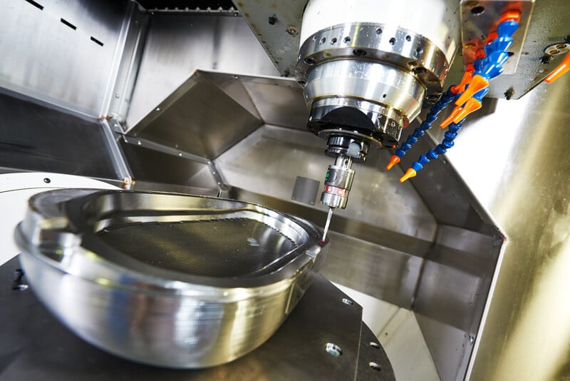
Using Spatial’s 3D InterOp, your team can build metrology software that generates measurement plans and preserves design intent by importing PMI (Product Manufacturing Information) from 3D CAD models. Our customers can achieve up to 90% time savings when utilizing PMI to create an inspection plan.
Proven Application Development Framework
Spatial’s AGM, the Application Graphics Manager, is a complete 3D application development framework. It presents a versatile array of tools for crafting resilient 3D applications. This encompassing framework spans various layers of functionality, incorporating elements such as a user interface framework, intricacies of geometry undo/redo, the rendering engine, and everything in between — while ensuring seamless integration with all other Spatial SDKs.
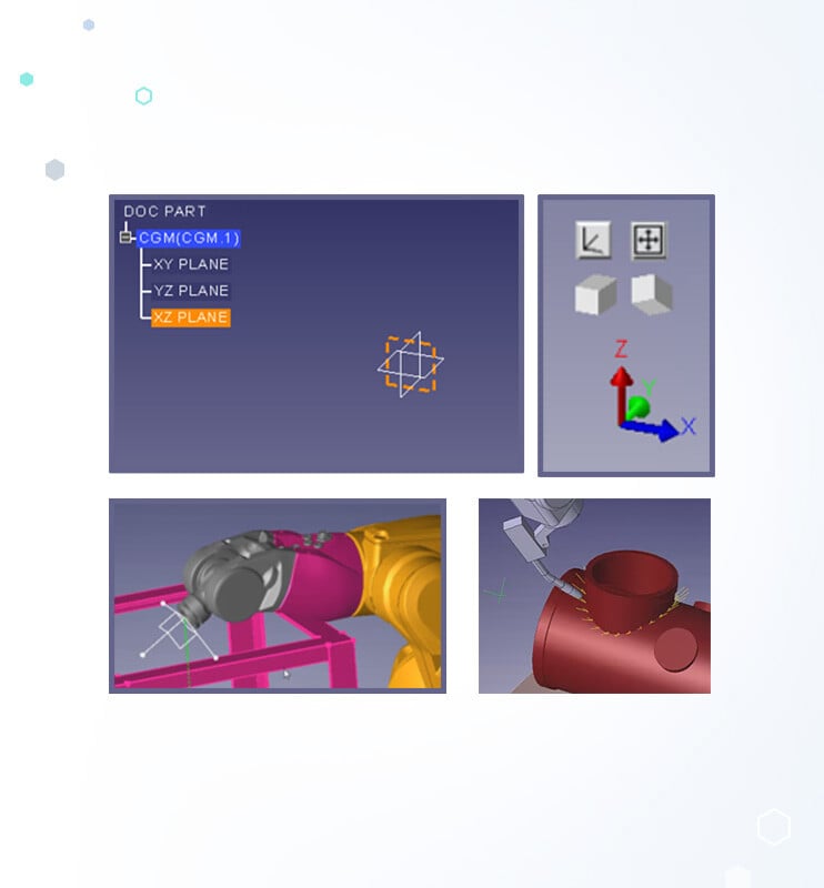
Geometric Constraint Solver
Constraint Design Solver (CDS) is a geometric constraint solver SDK that facilitates optimal part and assembly design. CDS simulates the solution of inverse kinematics of the CMMs and positions the positioning of objects on the CMM device with several under geometric constraints.
-2.webp?width=500&name=Additive-Manufacturing-spatial-feature%20(15)-2.webp)
1. CAD Data Import
- Fast Visualization Import
- Selective B-Rep Import
- Semantic and Graphical PMI
- CAD Associativity


2. Part Analysis
- PMI Analysis
- Feature Detection


3. Preparation
- Measurement Planning
- Feature Selection
- Dimensions
- Geometry Sampling


4. Processing
- Inverse Kinematics
- Clash Detection


5. Post-Processing
- Distance Calculations
- Result Visualization
- Report Generation

Features Built for Metrology Workflows
Spatial’s solutions have specific built-in functionality that targets the unique
needs of the metrology industry. Select capabilities include advanced functionality
for handling geometric data, support for large point clouds and support
of a rollback mechanism for handling undo/redo.
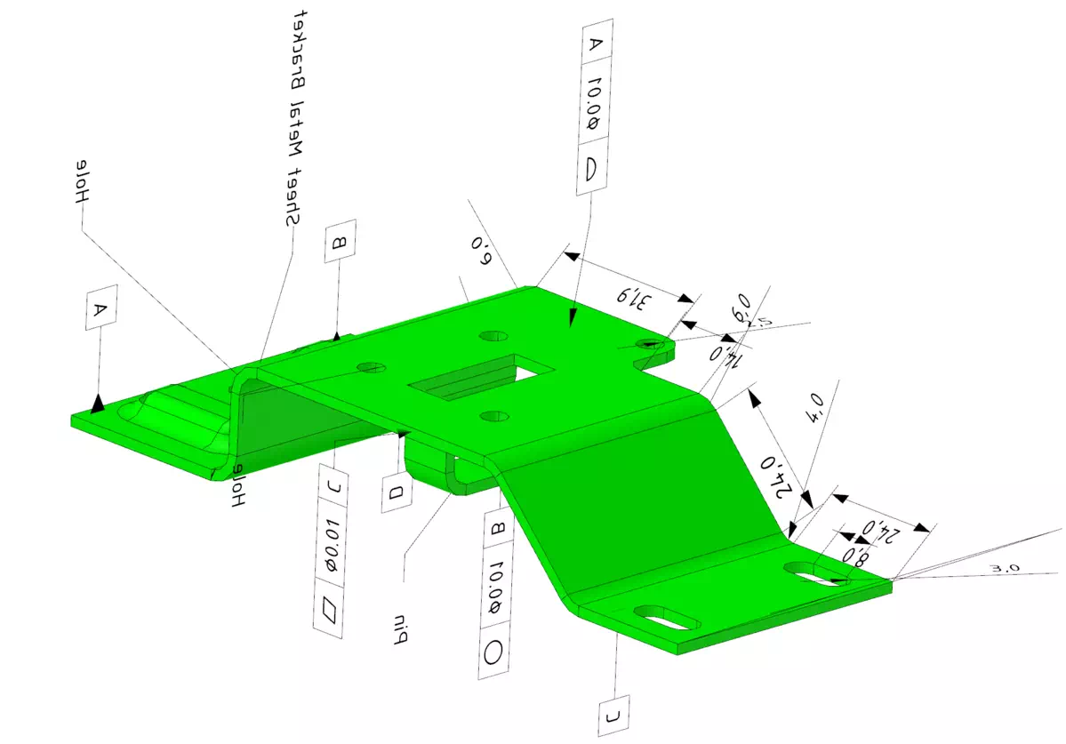
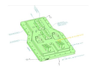
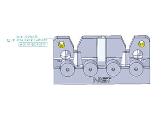
Capture Design Intent
Seamlessly access and utilize original CAD annotations directly within the CAD environment, ensuring precise dimensioning and geometric relationships. This feature allows for directly verifying engineering tolerances and specifications, enhancing the accuracy of measurements and analyses. It supports a comprehensive understanding of geometric tolerances, their types, values and the specific faces or edges they pertain to, facilitating a thorough and efficient validation process.
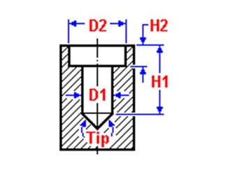
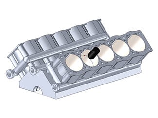
Part Analysis
Automate measurement planning and generate insightful reports with an intuitive, geometry-based feature detection system. By analyzing face combinations, this advanced algorithm identifies and categorizes features such as holes, pads, pockets, fillets and chamfers. It simplifies the measurement process by clearly defining which geometries to measure, including face details and axis orientation. Additionally, it provides parametric definitions to anticipate measurement outcomes, covering aspects like diameters, depths and hole types (blind or through), streamlining the analysis for accuracy and efficiency.

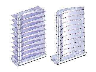
Generate Measurement Point
Precisely generate measurement points from the part's geometry by employing planar and non-planar slices as well as projection and offset operations to mark points on the model accurately. Efficiently create and optimize sensor paths on the nominal part. On parts, allowing for a detailed comparison of inspection measurement points against these curves, enhancing accuracy and ensuring quality control.
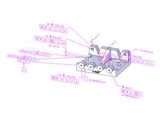
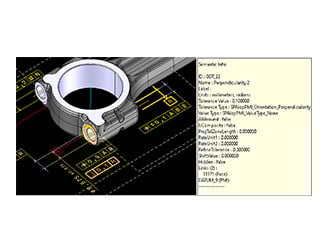
Annotation Analysis
Facilitate precise part positioning for measurements using reference faces and DATUM information. Further refine measurement workflows by employing
compound PMIs, enabling the automatic grouping of measurement activities. This integration between feature detection and compound PMIs allows the efficient measurement of features that share annotations.
Optimize Sensor Paths
Leverage model geometry to automate optimize the creation of sensor paths by querying geometric objects, where evaluators calculate normals and curvatures at specific positions. This process generates sensor paths as a sequence of points along faces or edges, ensuring thorough coverage. This ensures thorough coverage along faces and edges.
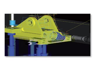
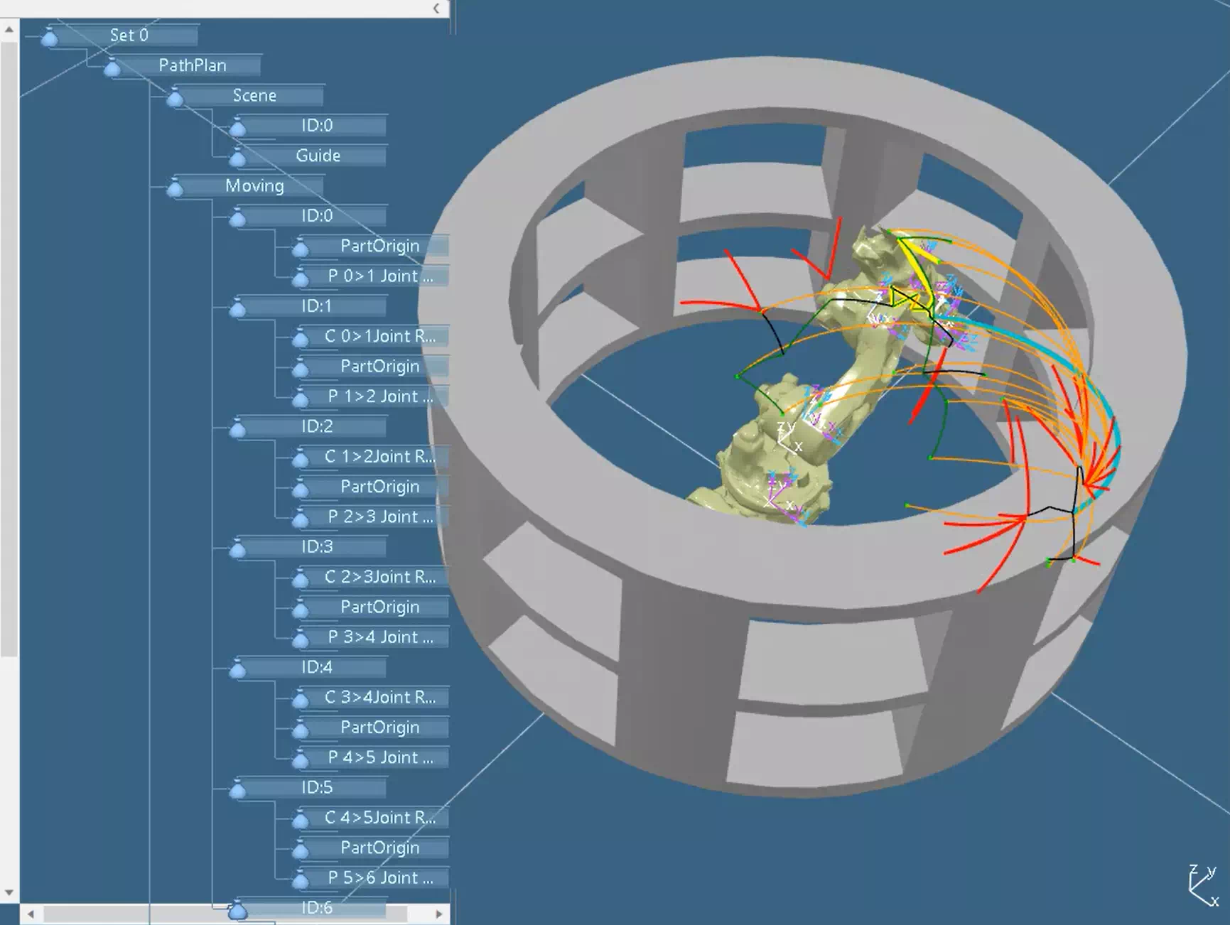
Enhance Operational Safety with Strategic Path Planning
Mitigate the risk of clashes during processing the measurement and inspection process by creating ‘no-go’ regions around workpieces and machinery. This is achieved by offsetting bodies and enlarging their volume by a predetermined distance to ensure a safe operational buffer. Additionally, compensate for the touch probe radius during path generation by offsetting faces, which accurately determines the center locations of the touch probes. This careful planning not only safeguards the equipment as well as the part to inspect but also maintains the integrity of the measurement process, ensuring precise and reliable results.
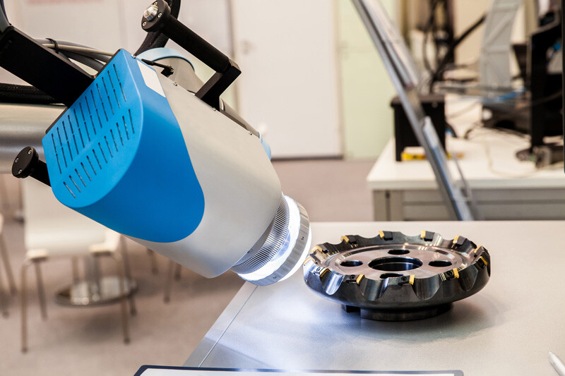
Collision Detection
Implement advanced collision detection algorithms to preemptively identify potential clashes between the probe, fixtures, work-pieces and machinery, ensuring the integrity of the equipment and the items being measured. Utilize fast, parallel processing techniques suitable for real-time applications to maintain operational flow without sacrificing safety. Through off-line path planning, validate measurement plans in advance to avoid any risk of gouging the work-piece. Robust inverse kinematics algorithms also simulate end-effector (probe) position along the object being measured.
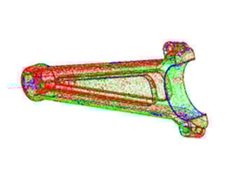
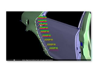
Optimize Data Integration With Advanced Point Cloud Processing
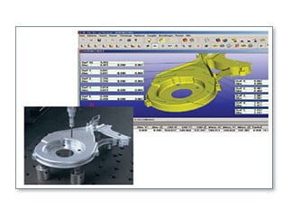
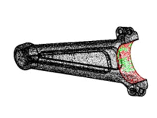
Utilize a two-stage alignment process combining inertia matrices and least squares fit to precisely align measured data with the 3D model. This method calculates distances for each point from the geometry, indicating their positional relationship with inside or outside status. Calculate the distances between the actual measurement points and the nominal part geometry and indicate for every measurement point its positional relationship with inside or outside status. Evaluate manufacturing accuracy by comparing measurements to tolerances
and identifying deviations such as ‘overcut’ or ‘undercut.’ Leverage a high-performance, parallelized architecture that efficiently handles large datasets, ensuring quick and scalable comparisons for effective analysis and quality control.

Our collaboration with Spatial now allows us to not only perform high-quality healing on STL files but, more importantly, to import various CAD formats directly.
Why Develop With Spatial SDKs?
translators, a robust meshing component, tight integrations with the renderer and a
time-saving application development framework.

Focus on Your Value-Add
-1.svg)
Faster Time to Market
.svg)
Improve User Experience
.svg)