What is a SOLIDWORKS file format?
SOLIDWORKS is a solid modeling CAD and CAE application developed by Dassault Systèmes. It is widely used for mechanical design, product development, tooling, manufacturing preparation, and engineering documentation.
SOLIDWORKS file formats are used to store different levels of design information. A single part file may contain solid bodies, surfaces, sketches, features, dimensions, materials, configurations, and custom properties. An assembly file can reference multiple part files and define how components are positioned, constrained, and related to each other. A drawing file contains 2D documentation derived from parts or assemblies.
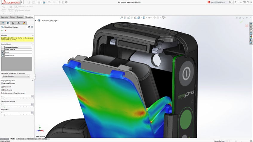
Because SOLIDWORKS is used across many engineering organizations, SOLIDWORKS file compatibility is important in multi-CAD environments. Applications that need to read, translate, visualize, manufacture, inspect, or simulate SOLIDWORKS data must handle both geometry and associated product structure accurately.
Native SOLIDWORKS file types
SOLIDWORKS uses several native file types depending on the type of document being created.
| File type |
Extension |
Purpose |
| SOLIDWORKS Part |
.sldprt |
Stores individual parts, including solid bodies, surfaces, sketches, features, configurations, and properties |
| SOLIDWORKS Assembly |
.sldasm |
Stores assemblies made from multiple parts or subassemblies, including mates, component references, and assembly structure |
| SOLIDWORKS Drawing |
.slddrw |
Stores 2D drawings, views, annotations, dimensions, and documentation derived from parts or assemblies |
| SOLIDWORKS Drawing Template |
.slddrt |
Stores drawing sheet format information and template data |
The relationship between these file types is important. A SOLIDWORKS assembly usually references part files rather than containing all part data as fully independent geometry. If referenced files are missing, moved, renamed, or versioned incorrectly, the assembly may not open or rebuild as expected.
What geometry and engineering data is stored in SOLIDWORKS files?
SOLIDWORKS files can contain more than visible geometry. Depending on the file type and workflow, they may include:
- B-Rep solid and surface geometry
- Feature history and parametric relationships
- Sketches, dimensions, and constraints
- Assembly structure and component references
- Mates and positioning information
- Configurations and design variations
- Materials and appearances
- Custom properties and metadata
- Drawing views, annotations, and dimensions
- PMI or manufacturing-related information, depending on the workflow
This makes SOLIDWORKS data more complex than a simple 3D shape file. A downstream application may need only the geometric model, while another workflow may require assembly hierarchy, metadata, configuration data, or manufacturing information.
Native, neutral, and proprietary CAD exchange
SOLIDWORKS can work with native SOLIDWORKS files as well as many neutral and proprietary CAD formats. Native SOLIDWORKS formats are best suited when users need to preserve the full design structure inside SOLIDWORKS, including features, assemblies, drawings, and configurations.
Neutral formats are commonly used to exchange geometry between CAD systems. Common examples include:
| Format |
Extension |
Typical use |
| STEP |
.stp, .step |
General CAD exchange for solid and assembly geometry |
| IGES |
.igs, .iges |
Legacy exchange format often used for curves and surfaces |
| STL |
.stl |
Mesh format commonly used for 3D printing and visualization |
| Parasolid |
.x_t, .x_b |
Geometry exchange using the Parasolid modeling format |
| ACIS SAT |
.sat |
Geometry exchange using the ACIS modeling format |
| DXF / DWG |
.dxf, .dwg |
2D drawings, profiles, and some 3D CAD exchange workflows |
Proprietary CAD formats may also be used in multi-CAD environments, such as files from CATIA, NX, Creo, Inventor, or Solid Edge. In these workflows, the goal is often to use third-party data without rebuilding the design from scratch.
Importing and exporting SOLIDWORKS data
When SOLIDWORKS data is imported into another application, the receiving software must interpret the model's geometry, topology, assembly structure, and metadata. This is not always straightforward because a SOLIDWORKS file may contain parametric features, configuration-specific geometry, references to external files, or information that is not supported by the target system.
When SOLIDWORKS data is exported to another format, the export process may preserve only part of the original information.
A STEP export may preserve precise B-Rep geometry and assembly structure, but it may not preserve the full parametric feature tree in the same way as the native SOLIDWORKS file. An STL export converts the model into a polygon mesh, which is useful for 3D printing but does not preserve exact analytic surfaces, feature history, or editable solid topology.
This is why file format selection matters. The best format depends on the downstream workflow: design collaboration, machining, simulation, visualization, 3D printing, inspection, archiving, or supplier exchange.
What are SOLIDWORKS files used for? Applications and industry use cases
SOLIDWORKS file formats are used throughout mechanical engineering and product development workflows.
| Domain |
How SOLIDWORKS files are used |
| Mechanical CAD |
SLDPRT files are used to design individual components such as housings, brackets, gears, fasteners, fixtures, and molded parts, with geometry, dimensions, features, materials, and design variations defined in the part file |
| Assembly design |
SLDASM files bring together multiple parts and subassemblies, allowing teams to validate fit, motion, component placement, interference, and product structure before manufacturing |
| Engineering documentation |
SLDDRW files are used to create manufacturing drawings, dimensions, notes, views, tolerances, and other information required for production or supplier communication |
| CAM and manufacturing |
Part and assembly data feed machining, tooling, mold design, fixture creation, and production planning. Downstream systems may need access to precise B-Rep geometry, hole features, surfaces, and manufacturing metadata |
| CAE and simulation |
Geometry is often simplified, repaired, defeatured, and meshed before analysis. Workflows may use the native model or a translated format depending on the application and level of detail required |
| Additive manufacturing |
Models are exported to mesh formats such as STL or 3MF. Before printing, the geometry may need to be checked for watertightness, wall thickness, mesh quality, and manufacturability |
| Multi-CAD collaboration |
Files are exchanged with suppliers, customers, or partner teams using other CAD systems, which makes accurate CAD translation and interoperability essential |
Relation to other concepts
Related glossary terms include:
Challenges or common pitfalls
A common issue with SOLIDWORKS files is assuming that all downstream applications can read the same information contained in the native file. A viewer, translator, CAM system, or simulation tool may support the geometry but not the full feature history, mates, configurations, drawing annotations, or metadata.
Assembly references can also create problems. A SOLIDWORKS assembly depends on its referenced part and subassembly files. If these files are missing, renamed, moved, or not packaged correctly, the assembly may open with unresolved components.
Another pitfall is treating CAD translation as lossless. Moving from SOLIDWORKS to STEP, IGES, STL, or another format can change what information is preserved. Exact solid geometry may become a mesh, feature history may be removed, and assembly intelligence may be simplified.
Version compatibility is also important. Newer SOLIDWORKS files may not always open in older versions of the software. Multi-CAD workflows should account for software version, supported file versions, and the capabilities of the receiving application.
Geometry quality can also affect downstream workflows. Imported or exported models may contain tolerance issues, missing faces, gaps, short edges, sliver surfaces, or non-manifold conditions. These problems can cause failures in meshing, machining, Boolean operations, or model validation.
Finally, users should choose exchange formats based on the intended use:
- STEP for precise CAD exchange
- STL for 3D printing
- DXF or DWG for 2D profiles and drawings
- Native SOLIDWORKS files when preserving the original design structure is required
How Spatial Helps
Spatial's 3D InterOp supports CAD interoperability workflows for applications that need to read, write, or translate SOLIDWORKS and other engineering file formats. For developers building CAD, CAM, CAE, additive manufacturing, metrology, robotics, or visualization software, this helps integrate SOLIDWORKS data into broader multi-CAD workflows.
3D InterOp can support the translation of precise CAD geometry, assemblies, and relevant product data where supported by the source and target formats. This is important when applications need to import SOLIDWORKS models, preserve useful engineering information, and prepare the data for downstream use, which the Data Prep add-on handles through simplification, optimization, and repair.
Spatial modeling technologies such as 3D ACIS Modeler and CGM Modeler can also support applications that need to perform geometric operations after import. In a typical workflow, SOLIDWORKS data may be read through an interoperability layer, checked or healed, and then used for modeling, meshing, manufacturing, inspection, or visualization.
For software teams, using a CAD interoperability SDK can reduce the need to build and maintain individual translators for each CAD format. It can also help improve consistency when handling geometry, topology, assemblies, metadata, and multi-CAD exchange workflows. Our 3D InterOp ebook covers this in more detail.

-1.webp)


















.png?width=450&name=AdobeStock_188705270%20(2).png)