In computer-aided design (CAD), hybrid modeling is the practice of using different modeling techniques (using different rule sets) in the same workflow. In a hybrid modeling approach, four types of modeling data can be represented:
BRep (Boundary Representation) model data
Polygon model data
Point cloud data (3D scanned objects)
Voxel data (3D pixels for volumetric imaging)
Much of the traditional 3D software is specialized to handle one type of modeling data and may lack the ability to interpret other formats, just as some CAD file formats are limited to certain types of modeling data.
Before we explain why, we need to understand what each modeling format is.
Want to learn about other 3D modeling techniques ?
Hybrid modeling is a CAD and engineering software workflow that combines multiple forms of 3D representation, such as precise B-Rep geometry, polygon meshes, point clouds, and voxel data. It allows an application or workflow to use the most appropriate representation for each task, rather than forcing all geometry into a single modeling method.
In CAD, CAE, CAM, scanning, and visualization workflows, different modeling techniques describe geometry in different ways. A B-Rep model represents exact boundaries through faces, edges, vertices, curves, and surfaces. A polygon model approximates shape using triangles or polygons, a process also known as faceting. A point cloud captures a scanned object as a dense set of measured points. A voxel model represents volume as a grid of discrete 3D cells.
Hybrid modeling brings these representations into a connected workflow. For example, a mechanical part may be designed as a B-Rep solid, converted to a polygon mesh for visualization, compared with point cloud scan data for inspection, and simplified or meshed for simulation. The goal is not to replace one representation with another, but to preserve the strengths of each representation at the stage where it is most useful.
Representation
How it describes geometry
Common uses
Key trade-off
B-Rep
Mathematical surfaces, curves, faces, edges, vertices, and topology
Captures real objects quickly, but lacks explicit surfaces and topology
Voxel data
Discrete volumetric cells arranged in a 3D grid
Volumetric imaging, scientific data, material simulation, some additive workflows
Useful for volume and field data, but can become very large at high resolution
B-Rep models
Boundary representation, or B-Rep, is the dominant representation in mechanical CAD. It defines the boundary between solid and non-solid space using mathematically precise geometry and explicit topology. This makes B-Rep suitable for manufacturing because edges, faces, holes, blends, and surfaces can be evaluated with engineering precision.
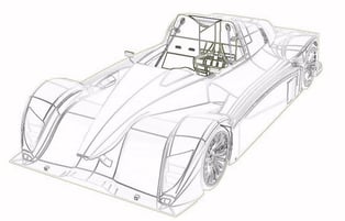
A B-Rep model describes a part through mathematically defined boundaries rather than display polygons.
Advantages
Limitations
Mathematically precise representation of design intent and engineered geometry.
Can be data-heavy and sensitive to geometric tolerance issues.
Curves and surfaces remain exact when zoomed or evaluated at different scales.
Not always the most efficient representation for visualization, animation, or real-time rendering.
Well suited to manufacturing, CAM, inspection, and precise downstream operations.
Organic or highly irregular natural shapes can be difficult to model directly with exact surfaces.
Polygon models
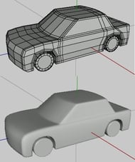
Polygonal modeling represents objects as a network of flat facets, usually triangles or polygons. Increasing the polygon count can make a model appear smoother, but the underlying model remains an approximation of the intended surface. This is why polygon models are widely used for rendering, animation, and visualization, but are less suitable as the primary representation for precise manufacturing geometry.
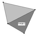
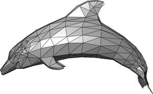
A polygon model approximates curved shape using many connected facets.Individual triangular faces are the basic building blocks of many mesh models.
Mesh models can represent organic shapes efficiently, but precision depends on mesh resolution.
Advantages
Limitations
Efficient for rendering and visualization because graphics hardware is optimized for triangles.
Approximate by nature; curved geometry depends on mesh resolution.
Good for organic shapes, deformation, animation, and visual design.
May not contain the topology, analytic surfaces, or feature information needed for CAD/CAM.
Can be exchanged easily in workflows that use formats such as STL or OBJ.
High-fidelity models can require large polygon counts and manual cleanup.
Point cloud models
Point cloud data is commonly produced by 3D scanning, LiDAR, photogrammetry, and metrology systems. Instead of surfaces or faces, the object is represented by many discrete points in 3D space. With sufficient density and quality, a point cloud can capture complex real-world geometry such as cast parts, buildings, turbine blades, or human faces.
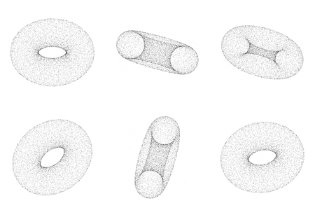
A point cloud represents shape as many measured points rather than explicit surfaces.
Advantages
Limitations
Captures complex real-world objects quickly, especially when generated by scanning.
Does not inherently define surfaces, faces, edges, or solid topology.
Useful for inspection, reverse engineering, and comparison between as-designed and as-built data.
Can be noisy, incomplete, or difficult to align without preprocessing.
Can support downstream reconstruction, meshing, or simulation preparation.
Converting point clouds into accurate B-Rep or clean mesh models can be difficult.
Voxel models
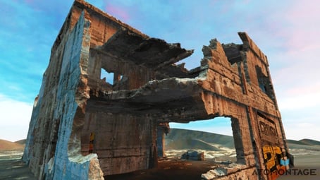
A voxel is a volumetric pixel: a discrete cell in a 3D grid. Voxel models are useful when the volume of an object matters, not only its surface. They are common in medical imaging, geoscience, volumetric simulation, material modeling, and workflows where density, porosity, or internal structure must be represented.
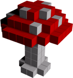
Voxel data represents volume through discrete 3D cells.The voxel concept is analogous to pixels in 2D images, extended into 3D space.
High-resolution voxel scenes can represent complex volumetric detail, but data size and rendering cost increase quickly.
Advantages
Limitations
Well suited to volumetric data, internal structures, fields, and material distributions.
Less mathematically exact than B-Rep for precise mechanical surfaces.
Useful for simulations that depend on volume, density, particles, or spatial fields.
High-resolution voxel data can be large and computationally expensive.
Can model organic and natural structures without relying on analytic surfaces.
Authoring and editing complex engineering parts directly as voxels is not always practical.
How a hybrid modeling workflow works
Traditional workflows often require engineers to move between separate tools and convert data manually when switching between B-Rep, polygon, point cloud, and voxel representations. Each conversion can introduce errors, lose metadata, or require manual repair.
A hybrid modeling workflow reduces this friction by allowing multiple representations to coexist or move through a controlled conversion process. A typical workflow might look like this:
Import or create a precise B-Rep model for design and manufacturing intent.
Generate a polygon mesh for rendering, lightweight collaboration, or additive manufacturing preparation.
Bring in point cloud scan data to compare the manufactured or scanned object against the CAD model.
Create analysis-ready mesh or volumetric data for simulation, material modeling, or field-based calculations.
Map results, corrections, or design changes back into the engineering model when appropriate.
The value of hybrid modeling is not simply that different data types can be opened in the same application. The technical value comes from maintaining usable relationships between representations, controlling tolerance and approximation, and preserving enough information for downstream engineering operations.
What is hybrid modeling used for? Applications and industry use cases
Hybrid modeling is especially useful in engineering workflows where a single representation cannot satisfy every requirement. In practice, many product development processes move between precise CAD geometry, mesh-based models, scan data, and simulation-ready representations depending on the task.
Domain
How hybrid modeling is used
Mechanical CAD and product design
Engineers rely on B-Rep geometry to define accurate parts and assemblies, then use mesh representations for visualization, rendering, or downstream analysis. The same model may need to be simplified or defeatured before simulation, especially when small details such as fillets, holes, or fasteners do not affect the engineering result but make meshing more difficult
Precise B-Rep geometry defines machinable surfaces, edges, and tolerances, while mesh or scan data supports verification, inspection, and comparison against manufactured parts
Parts move from precise CAD geometry to mesh-based formats such as STL, then require repair, validation, orientation, support generation, or build preparation before they can be manufactured reliably
Point cloud data captured from 3D scanning is aligned with existing CAD geometry, reconstructed into surfaces, or compared against nominal models to identify deviations
CAD or BIM geometry is combined with point clouds, terrain models, or voxel-like volumetric data to support measurement, inspection, spatial analysis, and visualization
Challenges or common pitfalls
One common mistake in hybrid modeling is assuming that all geometric representations carry the same type of information. A point cloud, for example, may describe the position of millions of measured points, but it does not contain B-Rep topology, analytic surfaces, or design intent. Similarly, a polygon mesh can represent shape visually, but it usually does not preserve feature history, parametric constraints, or exact manufacturing geometry.
Conversion between representations should also not be treated as lossless. Moving from B-Rep to mesh introduces approximation because exact surfaces are discretized into triangles or other elements. Reconstructing B-Rep geometry from a mesh or point cloud is even more difficult, since the software must infer surfaces, edges, and topology from incomplete or noisy data. Details can be simplified, distorted, or lost during this process.
Tolerance management is another critical issue. Hybrid workflows depend on controlled tolerances for surface fitting, geometry healing, meshing, Boolean operations, scan alignment, and model comparison:
If tolerances are too loose, important details may be merged or removed.
If they are too strict, otherwise usable geometry may fail to convert, repair, or mesh correctly.
A further pitfall is using the wrong representation for the task. B-Rep geometry is generally appropriate when exact surfaces, edges, and manufacturing intent matter. Meshes are often better suited to rendering, visualization, 3D printing preparation, or certain simulation workflows. Point clouds are useful for captured real-world data, while voxel grids are better suited to volumetric or material-based simulation. Hybrid modeling is effective when each representation is used where it provides the most value.
Performance and data size can also become significant constraints. Dense point clouds, high-polygon meshes, and high-resolution voxel grids can be expensive to store, display, query, and process. Without simplification, segmentation, or level-of-detail strategies, hybrid workflows can quickly become difficult to scale.
Finally, hybrid workflows can lead to the loss of engineering intent. Once feature history, constraints, PMI, metadata, or assembly structure are removed from a model, they may be difficult or impossible to reconstruct automatically. Developers and engineers should treat conversion not only as a geometric operation, but also as a data preservation problem.
How Spatial Helps
Spatial technologies support software developers building applications that need to combine precise CAD geometry, CAD data exchange, meshing, and visualization in engineering workflows.
3D ACIS Modeler and CGM Modeler provide geometric modeling capabilities for applications that need to create, edit, and manage precise 3D geometry. In hybrid workflows, this type of modeling foundation is important when B-Rep geometry must remain usable for design, manufacturing, and downstream engineering operations.
3D InterOp supports CAD data exchange by helping applications read and translate data from major CAD formats. This is relevant to hybrid modeling because imported geometry often needs to be reused in another representation or prepared for visualization, simulation, manufacturing, or inspection. The Data Prep add-on simplifies, optimizes, and repairs that CAD data before it moves downstream.
Spatial meshing and visualization technologies also fit into hybrid workflows where CAD geometry must be prepared for CAE, displayed interactively, or converted into representations suitable for downstream processing. The exact architecture depends on the application, the source data, and the level of precision required.
Discover Spatial Solutions
3D Modeling
We’re proud to have pioneered the development of geometry kernels with ACIS. Today, we offer solutions to support your 3D geometry representation needs. Whether you require a continuous or discrete B-Rep modeler, we have a solution for your application’s specific needs.
As the first company to offer a CAD interoperability SDK, we now provide industry-leading solutions to translate data, and read major CAD files and metadata. Enable your customers to work with imported 3D data as if created natively in your own application or export data into various CAD formats.
Create high-performance, interactive visualizations with our 3D visualization SDKs. HOOPS solutions allow you to harness the industry’s most powerful, portable and complete graphics development components for creating 3D applications.
Enhance the accuracy and performance of your simulations with our meshing SDKs for CAE. Experience automatic and reliable meshing with controls to guarantee accurate and performant simulations for any CAE workflow.
Discover how our robotics-focused SDKs enable high-precision 3D CAD data import and conversion, data simplification, collision checking, 3D shape modeling, and web-based visualization.
COSCOM needed an efficient solution to manage massive CAD data volumes in their digital twin application while maintaining precision for collision detection and machine simulation in CNC machining processes.
TraceParts, a well-known CAD content supplier, integrates robust 3D visualization into their online 3D part viewer to enhance customer ordering experience.
Ebooks whitepaper /
3d interoperability /
Robotics /
Interop
Discover how our robotics-focused SDKs enable high-precision 3D CAD data import and conversion, data simplification, collision checking, 3D shape modeling, and web-based visualization.
COSCOM needed an efficient solution to manage massive CAD data volumes in their digital twin application while maintaining precision for collision detection and machine simulation in CNC machining processes.
TraceParts, a well-known CAD content supplier, integrates robust 3D visualization into their online 3D part viewer to enhance customer ordering experience.
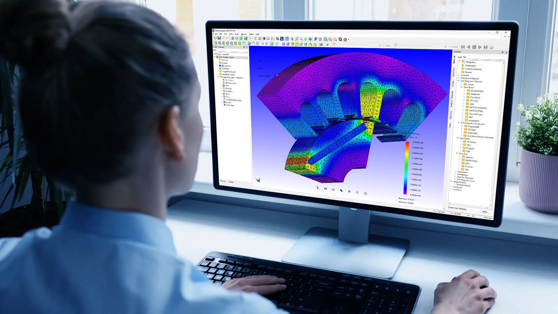
JMAG, a simulation software for electromechanical design developed by JSOL CORPORATION, required 3D geometry handling, reliable CAD import across multiple formats, interactive operations, and defeaturing capabilities for analysis.
Coreform was poised to make a real impact on the CAE world. By integrating specific Spatial SDKs customized to their needs, Coreform closed the circle on its revolutionary software.
Case study /
3d interoperability /
Metrology /
3d interop
LK Metrology was on a quest to maintain precision for their Coordinate Measuring Machines. They improved core application functionality through a development partnership with Spatial.
Coreform was poised to make a real impact on the CAE world. By integrating specific Spatial SDKs customized to their needs, Coreform closed the circle on its revolutionary software.
Case study /
3d interoperability /
Metrology /
3d interop
LK Metrology was on a quest to maintain precision for their Coordinate Measuring Machines. They improved core application functionality through a development partnership with Spatial.
Discover how our robotics-focused SDKs enable high-precision 3D CAD data import and conversion, data simplification, collision checking, 3D shape modeling, and web-based visualization.
Read now
Ebooks whitepaper /
3d interoperability /
Cad /
Interop
Learn how to apply surface and volume meshing best practices and integrate advanced features like mesh adaptation and boundary layers into your workflow. Discover how meshing techniques can optimize performance, accelerate simulations, and streamline your development process.
Read now
Webinar /
3d interoperability /
Simulation /
Data prep
Explore how the Data Prep add-on for 3D InterOp can assist you in managing CAD files and complex data within your visualization, simulation, and costing workflows.
Explore how the Data Prep add-on for 3D InterOp can assist you in managing CAD files and complex data within your visualization, simulation, and costing workflows.

-1.webp)












.png?width=450&name=AdobeStock_188705270%20(2).png)