What is a clash?
A clash is not limited to a simple geometric overlap. In BIM workflows, it usually refers to a conflict between model elements from different disciplines, such as structure, HVAC, plumbing, or electrical systems, when they intersect physically or break a rule about clearance, access, or sequencing.
THERE ARE 3 TYPES OF CLASHES:
.png?width=512&height=142&name=unnamed%20(1).png)
A hard clash happens when two components physically intersect, such as ductwork passing through a beam or piping crossing a wall. This is the most direct type of interference and is usually detected through geometry-based checks, sometimes combined with rule-based logic.
A soft clash happens when objects do not strictly intersect but still violate a required buffer zone, clearance envelope, or service space. A common example is leaving too little room for maintenance access around equipment, even though the geometry does not visibly collide.
A workflow clash, sometimes described as 4D clash detection (the "4th dimension" being time/schedule), does not come from pure object interference. Instead, it results from conflicting schedules, deliveries, activity timing, or other process information, such as equipment installation being planned before the required materials are available.
How does clash detection work?
At a geometric level, clash detection checks whether one body comes within a specified tolerance of another. This is faster than a full Boolean intersection because the software only needs to confirm that an interaction exists, not calculate the overlap volume.
.png?width=512&height=208&name=unnamed%20(2).png)
A common first step is a bounding-box check. If the bounding boxes of two elements do not overlap, the software can quickly reject them as a non-clashing pair. Detailed analysis is then reserved for the smaller set of candidate objects that may actually interfere. This matters in large BIM datasets, where checking every object pair precisely would be too expensive computationally.
👉 Learn more: Clashing Geometry in BIM Datasets
What Is Clash Detection in BIM Used For?
Clash detection is widely used in BIM coordination to compare federated models from architecture, structure, MEP, and specialist systems before construction begins. Its main value is catching incompatibilities early enough to reduce rework, delays, and coordination errors across disciplines. It is also useful in broader engineering software workflows wherever large 3D datasets must be checked for interference, clearance, or fit. Similar logic applies in plant design, digital mock-up, machinery layout, and simulation preparation, where identifying unwanted contact or insufficient spacing can prevent later failures in manufacturing, installation, or operation. After clashes are found, teams often create issue reports and track them through coordination workflows. buildingSMART's BCF standard is commonly used for this kind of model-based communication, linking clash locations with comments, statuses, and responsibilities so issues can be resolved systematically.
Challenges or Common Pitfalls
One common mistake is to treat every reported clash as equally important. In real projects, some are true design errors, some are acceptable interfaces, and some are false positives caused by tolerances, model simplification, or incomplete coordination rules. That is why automated detection still needs human review. Another pitfall is relying only on exact geometric intersection. Many coordination problems are actually soft clashes involving access, installation space, or maintenance clearance, so a purely geometry-only approach can miss issues that matter operationally. Data quality is also a recurring challenge. Clash detection depends on complete and reliable model geometry, metadata, and discipline coordination. If imported BIM or CAD data is incomplete, poorly translated, or insufficiently repaired, clash results may be noisy or misleading. For workflow clashes, the challenge is different: the difficulty is not geometry but synchronization of project information. Timing conflicts, delivery dependencies, and sequencing constraints require application logic above the geometry layer, often tied to scheduling and issue-management systems.
How Spatial Helps
Our SDKs address three parts of the clash-detection workflow that application developers need to get right: bringing multi-source data in, preparing it for analysis, and letting users visualize and interrogate results.
- Data ingestion. 3D InterOp reads and writes around 30 CAD, BIM, mesh, and visualization formats, including IFC, Revit, DXF/DWG, CATIA, SOLIDWORKS, NX, STEP, and many others. It supports selective import, product structure handling, and automatic geometry healing, so developers can bring federated project data into a single, consistent application workflow. For clash detection, that reliability at the import stage matters: if the geometry or metadata comes in broken, everything downstream is suspect.
- Model preparation. Data Prep, our add-on for 3D InterOp, goes further by applying repair, stitching, defeaturing, instancing, and removal of hidden objects during import. Clash analysis is only as trustworthy as the model being checked, and cleaning up geometry before coordination reduces false positives and noisy results.
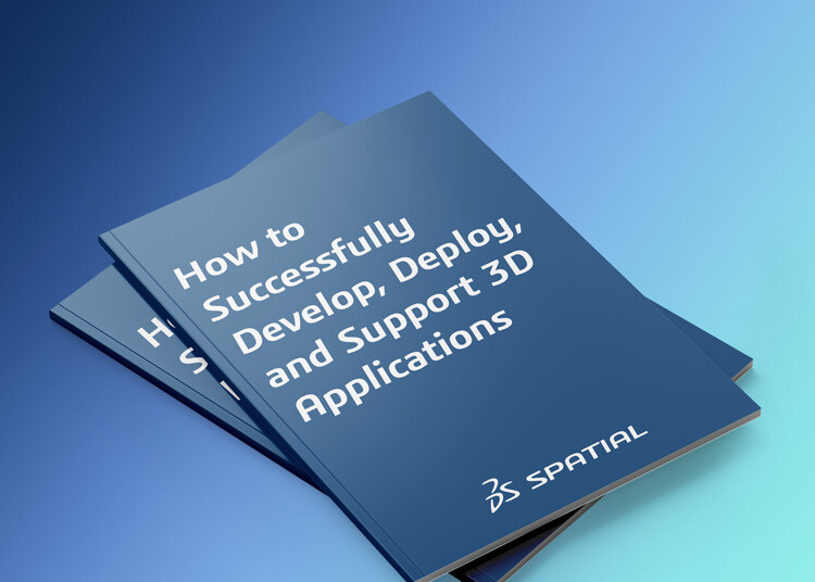
- Visualization and geometric analysis. HOOPS Visualize and Hoops Visualize Web includes clash-detection capabilities designed for both static and dynamic scenes, so developers can build interactive review tools where users see and navigate interference results in real time. On the modeling side, ACIS Polyhedra supports clash-detection queries on polyhedral models, along with distance calculations, wall thickness analysis, and mass properties — the kind of geometric interrogation that clash workflows frequently require.
Together, these give developers a foundation for applications that import, clean, visualize, and analyze large 3D datasets for interference and clearance. Workflow clashes — schedule conflicts, delivery sequencing, timing dependencies — sit outside the geometry layer. Our SDKs handle the 3D side of the problem; the scheduling and issue-tracking logic typically lives in the surrounding application, often alongside standards like BCF for structured communication and resolution tracking.

-1.webp)


.png?width=450&name=AdobeStock_188705270%20(2).png)


