Technical Explanation

What is meshing in engineering and simulation?
In engineering analysis, physical problems such as stress, heat transfer, or fluid flow cannot be solved directly on exact CAD geometry.
Meshing converts this geometry into a finite set of elements that approximate the original shape, allowing numerical solvers to compute results at each element and node.
The structure, density, and quality of the mesh directly influence simulation accuracy, stability, and performance.
What are the different types of meshing?
Several types of meshes are used depending on the simulation objective, the most common ones are:
-
Surface meshing
Uses 2D elements (triangles or quadrilaterals) to represent boundaries.
Commonly used for visualization, CFD boundary conditions, and lightweight analysis.
-
Volume meshing
Uses 3D elements (tetrahedra, hexahedra, prisms, pyramids, etc) to fill a solid volume.
Required for most FEA and CFD simulations.
-
Structured meshing
Follows a regular, grid-like topology.
Offers high numerical accuracy but is difficult to apply to complex geometries.
-
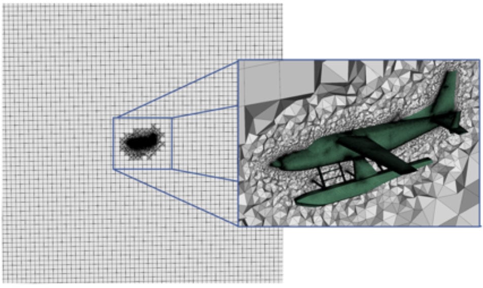
Unstructured meshing
Uses irregular element layouts that adapt to complex shapes.
Widely used in industrial CAE due to flexibility and automation.
What is the importance of meshing in CFD and FEA?
In both Computational Fluid Dynamics (CFD) and Finite Element Analysis (FEA), the mesh defines how physical equations are solved.
A high-quality mesh:
-
Accurately captures geometric features and curvature
-
Provides sufficient resolution in critical regions
-
Enables stable and convergent numerical solutions
Poor mesh quality can lead to inaccurate results, solver instability, or excessive computation time.
As a result, meshing is often one of the most critical—and time-consuming—steps in simulation workflows.
Key meshing parameters and quality criteria
Mesh quality is evaluated using several criteria, including:
-
Element size and distribution
-
Aspect ratio and skewness
-
Smooth transitions between fine and coarse regions
-
Boundary conformity to the original CAD geometry
Careful control of these parameters helps ensure reliable, repeatable and performant simulation results.
Optimizing meshes
Mesh optimization focuses on achieving the best balance between accuracy and computational efficiency.
Rather than simply increasing mesh density everywhere, optimization strategies aim to place elements where they matter most.
Common mesh optimization techniques include:
-
Local refinement in regions of high stress, curvature, or flow gradients
-
Adaptive meshing, where the mesh evolves based on simulation results
-
Element quality improvement, such as smoothing or re-shaping poorly formed elements
-
Geometry simplification (defeaturing) to remove small details that do not affect simulation outcomes
Optimized meshes reduce solver time and memory usage while maintaining accurate results.
How to Generate Accurate, Lightweight Meshes for Simulations
Generating accurate yet lightweight meshes is a key objective in modern CAE workflows.
This typically involves:
-
Preparing CAD geometry
Simplifying or defeaturing geometry to remove unnecessary details while preserving functional features.
-
Controlling mesh density
Applying fine meshes only where required and coarser meshes elsewhere.
-
Preserving geometric fidelity
Reducing mesh size or using high order elements to ensure the mesh accurately follows CAD boundaries, curvature, and topology.
-
Balancing accuracy and performance
Reducing element count without compromising simulation reliability.
Accurate, lightweight meshes enable faster simulations, lower computational costs, and more efficient design iterations
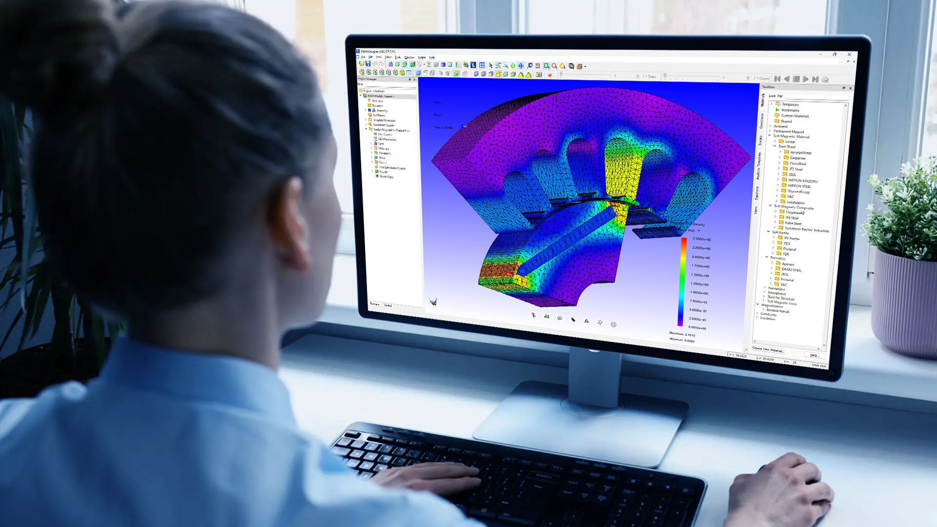
Applications and Industry Use Cases
Meshing is used across a wide range of engineering and industrial applications:
-
FEA – structural, thermal, vibration, and fatigue analysis
-
CFD – airflow, fluid dynamics, and heat transfer simulation
-
EDA – electromagnetic field, wave propagation, and electrostatic analysis
-
Manufacturing simulation – forming, molding, and machining processes
-
Digital mockups and visualization – lightweight representations of complex models
Industries such as aerospace, automotive, energy, and medical devices rely heavily on accurate meshing to validate designs before production.
Challenges or Common Pitfalls
Despite its importance, meshing presents several challenges:
-
Highly detailed CAD models may require extensive simplification
-
Poor element quality can compromise solver accuracy
-
Excessive mesh density increases computation time and memory usage
-
Inconsistent or corrupted CAD data can cause meshing failures
Achieving the right balance between robustness, accuracy, and performance is a core challenge in meshing.
How Spatial Helps
Spatial provides technologies that support robust meshing directly from CAD geometry.
By combining accurate CAD interoperability, geometry preparation, and controlled mesh generation based on solver requirements, Spatial enables developers to build reliable CAD-to-CAE pipelines.
Spatial’s approach supports:
-
Direct meshing from exact B-Rep geometry
-
Generation of high-quality, simulation-ready meshes
-
Consistent results across complex and multi-CAD datasets
This ensures meshing remains a dependable foundation for simulation and engineering analysis.

-1.webp)


.png?width=450&name=AdobeStock_188705270%20(2).png)


