What is solid modeling?
Solid modeling is the computer-based representation of three-dimensional objects as valid solids. Its purpose is not only to display a shape on screen, but to define a complete and unambiguous digital object with volume, boundaries, topology, and geometric properties.
A solid model can begin from a 2D sketch, a wireframe, or a basic geometric primitive such as a cube, sphere, cone, or cylinder. CAD users then transform these elements into more complex parts using operations such as extrusion, revolution, sweep, loft, fillet, chamfer, shell, or Boolean subtraction.
The key difference between solid modeling and simpler forms of 3D representation is that the model must remain geometrically valid. A solid model must define what is inside the object, what is outside, and how its faces, edges, and vertices are connected.
Solid modeling technology in a CAD environment
In a CAD environment, solid modeling gives designers and engineers a controlled way to manipulate 3D bodies without losing their solidity. A subtraction operation, for example, may appear to be a simple command for creating a hole, but the modeling system must update the affected faces, edges, and topology while preserving a valid closed body.
This is why solid modeling is more than shape visualization. It supports operations that depend on the object being a coherent volume, including mass property calculation, interference checking, section analysis, machining preparation, and simulation preprocessing.
Mathematical foundations of solid modeling
Solid modeling relies on mathematical representations of geometry and topology. In a CAD system, the software must calculate precise relationships between points, curves, surfaces, faces, edges, and volumes.
This precision is essential in engineering contexts. A mechanical component must not only look correct; it must have accurate dimensions, closed boundaries, and a coherent volume. Even small deviations can affect manufacturing, assembly, aerodynamics, structural behavior, or tolerance analysis.
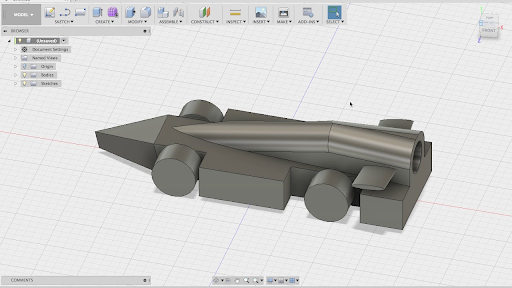
A simplified solid model used to illustrate precise CAD geometry.
A useful way to understand this precision is through a vehicle design example. If an automotive team is designing a race car component, the dimensions defined in the concept model must be represented accurately in the CAD model. Deviations of only a few millimeters can affect fit, aerodynamic behavior, or manufacturability. Solid modeling provides the computational framework needed to create and modify coherent engineering geometry with this level of control.
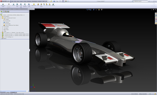
The same design concept as a higher-fidelity rendered model.
Euclidean space and coordinate-based modeling
Every design component with finite size and clear boundaries needs a mathematical space in which it can be represented. In CAD, this is typically a 3D coordinate environment based on Euclidean space.
Within this environment, objects can be positioned, measured, modified, and combined. Points define locations, curves define paths or profiles, surfaces define boundaries, and topology defines how these elements connect to form a valid solid.
Geometry, topology, and solidity
A solid model typically combines two types of information: geometry and topology.
| Concept |
What it describes |
Examples |
| Geometry |
The mathematical shape of the object |
Planes, cylinders, cones, spheres, NURBS surfaces, curves, analytic surfaces |
| Topology |
How those geometric elements are connected |
Which edges bound a face, which faces form a shell, whether that shell encloses a valid volume |
For a solid model to be reliable, it should be complete, valid, unambiguous, and volumetric. In practice, this means it should:
- Classify points as inside, outside, or on the boundary of the object
- Maintain consistent connectivity between vertices, edges, faces, and shells
- Provide one clear interpretation of the design
- Represent a real 3D body rather than only a visual outline or disconnected set of surfaces
Common solid modeling operations
Solid modeling systems allow users to create and modify objects while preserving their solid nature.
A Boolean subtraction can be used to cut a hole through a part. The CAD system must calculate the intersection between the cutting shape and the target body, remove the correct volume, rebuild the affected faces and edges, and verify that the resulting object is still a valid solid.
- Boolean union, subtraction, and intersection
- Extrude, revolve, sweep, and loft
- Fillet and chamfer creation
- Shelling and offsetting
- Draft application
- Face editing and direct modeling
- Feature creation and modification
- Mass property and volume calculation
Solid modeling compared with wireframe and surface modeling
| Approach |
What it represents |
Best suited to |
| Wireframe modeling |
Points, lines, and curves. Describes the outline or structure of a shape, but does not define surfaces or volume |
Outlines, construction geometry, structural reference |
| Surface modeling |
The external skin of an object. A surface model may not always define a closed solid |
Complex freeform shapes, industrial design, aerodynamic surfaces |
| Solid modeling |
A complete object with volume, boundaries, and topology |
Mechanical parts, assemblies, machining, simulation, design validation |
What is solid modeling used for? Applications and industry use cases
Solid modeling is widely used in mechanical CAD and product development because it provides a precise digital representation of manufacturable parts. Engineers can design components, define features, calculate dimensions, validate fit, and prepare models for downstream workflows.
| Domain |
How solid modeling is used |
| Automotive and aerospace design |
Creating components that must meet strict dimensional, structural, and aerodynamic requirements. Accurate solid geometry is essential when parts must be assembled, machined, tested, or simulated with minimal deviation from the intended design |
| Manufacturing and CAM |
Providing the geometric basis for machining operations, toolpath generation, fixture design, and production planning. Volume and boundary information supports hole recognition, pocket detection, stock removal, and collision checking |
| CAE and simulation |
Acting as the starting point for analysis. Geometry may be simplified, repaired, defeatured, or meshed first. A valid solid model improves the reliability of finite element analysis, computational fluid dynamics, thermal analysis, and other simulations |
| Additive manufacturing and 3D printing |
CAD geometry is converted into mesh formats such as STL. The quality of the original solid model strongly influences whether the printed part will be watertight, dimensionally accurate, and manufacturable |
| Architecture, product design, and visualization |
Interior design, consumer product design, prototyping, visualization, and digital content creation whenever accurate 3D objects are required |
Relation to other concepts
Related glossary terms include:
Challenges or common pitfalls
A common mistake is assuming that a model is a valid solid simply because it looks correct on screen. A visually complete object may still contain gaps, overlapping faces, non-manifold edges, missing topology, or inconsistent surface orientation. These issues can cause failures during Boolean operations, meshing, machining, or 3D printing.
Another challenge is maintaining geometric validity during complex operations. Fillets, shells, offsets, and Boolean operations can fail when the model contains small faces, sharp transitions, self-intersections, or tolerance inconsistencies. The more complex the geometry becomes, the more important robust modeling algorithms and careful tolerance management are.
Solid modeling can also become difficult when working with highly organic or freeform shapes. Surface modeling or hybrid workflows may be more appropriate during early shape exploration, while solid modeling becomes critical when the design must be engineered, validated, or manufactured.
Interoperability is another frequent issue. When a solid model is exchanged between CAD systems, the receiving application may interpret geometry, topology, tolerances, or metadata differently. This can lead to missing faces, broken solids, or loss of design intent.
Finally, solid models may contain more information than downstream workflows require. For simulation or manufacturing, small details such as tiny fillets, holes, threads, or cosmetic features may need to be removed or simplified to improve performance and avoid unnecessary complexity.
How Spatial Helps
Spatial provides modeling and interoperability technologies that support solid modeling workflows in engineering software applications.
3D ACIS Modeler and CGM Modeler provide geometric modeling capabilities for applications that need to create, edit, and manage precise 3D geometry. These technologies can support solid modeling operations such as body creation, topology management, Boolean operations, and geometry modification within CAD, CAM, CAE, and related applications. For parametric part and assembly design, Spatial also offers the Constraint Design Solver.
3D InterOp supports CAD data exchange workflows by helping applications read and translate solid models from multiple CAD formats. This is important when imported geometry must be used reliably in downstream modeling, manufacturing, simulation, or visualization workflows.
Spatial technologies can also support workflows where solid models need to be checked, repaired, simplified, or prepared for meshing, with the Data Prep add-on handling simplification and repair. This helps developers build applications that work with engineering geometry across design, analysis, and manufacturing processes.

-1.webp)
















.png?width=450&name=AdobeStock_188705270%20(2).png)