What is a sweep in CAD?
A sweep operation starts with two main inputs:
| Input |
Role |
| Profile |
The cross-section that will be moved through space |
| Path |
The curve, edge, or trajectory that the profile follows |
As the profile travels along the path, the CAD system generates the resulting 3D surface or solid. Onshape's documentation describes this as sweeping a profile along a path to create a swept solid, surface, or thin solid.
How does a sweep work?
In a typical workflow, the user sketches or selects a profile, then selects a path. The CAD system computes the shape created by carrying the profile along that trajectory while following the orientation rules defined by the sweep settings.
The path can be a simple line, an arc, a spline, a model edge, or a more complex curve. Some systems also support profile controls such as orientation, twist, scale, or lock direction, which let the profile change or rotate as it follows the path.
Open vs. closed profiles
The type of profile affects the result. A closed profile can usually create a solid sweep, such as a pipe, cable, or rib. An open profile is often used to create a swept surface or a thin solid, depending on the modeling system and the selected options.
Sweep vs. extrusion and lofting
A sweep is related to extrusion and lofting, but it is not the same operation.
| Operation |
How it creates geometry |
Typical use |
| Extrusion |
Pushes a profile in a straight direction |
Prismatic parts, bosses, pads, simple cuts |
| Sweep |
Moves a profile along a path |
Pipes, rails, cables, grooves, handles |
| Lofting |
Connects multiple profiles with a smooth transition |
Organic shapes, ducts, aerodynamic surfaces |
A sweep is especially useful when the profile must follow a curved or non-linear trajectory rather than a straight direction.
Applications and Industry Use Cases
Sweep operations are widely used in mechanical design, industrial equipment, architecture, AEC/BIM, consumer product design, and manufacturing preparation.
| Use case |
Example |
| Pipes and tubes |
Sweeping a circular profile along a routed path |
| Cables and wiring |
Modeling harnesses or routed cable paths |
| Rails and handles |
Creating ergonomic or structural curved parts |
| Grooves and channels |
Cutting swept slots or guide paths |
| Moldings and trims |
Sweeping architectural profiles along edges |
| Threads and helices |
Sweeping a profile along a helical path |
For software developers, sweep is a fundamental modeling operation because it requires robust geometry construction, path handling, profile orientation, and topology generation.
Challenges or Common Pitfalls
| Pitfall |
What to keep in mind |
| Profile too large for the path curvature |
The swept geometry may self-intersect or create invalid topology. |
| Poor profile orientation |
If the profile isn't aligned to the start of the path, the sweep may twist, shift, or produce an unexpected result. Many systems recommend placing the profile on a plane normal to the start of the path. |
| Sharp corners, high curvature, or closed loops |
Complex splines and tight geometry demand close attention to path continuity, profile constraints, tolerance settings, and how the system handles twisting or scaling. |
How Spatial Helps
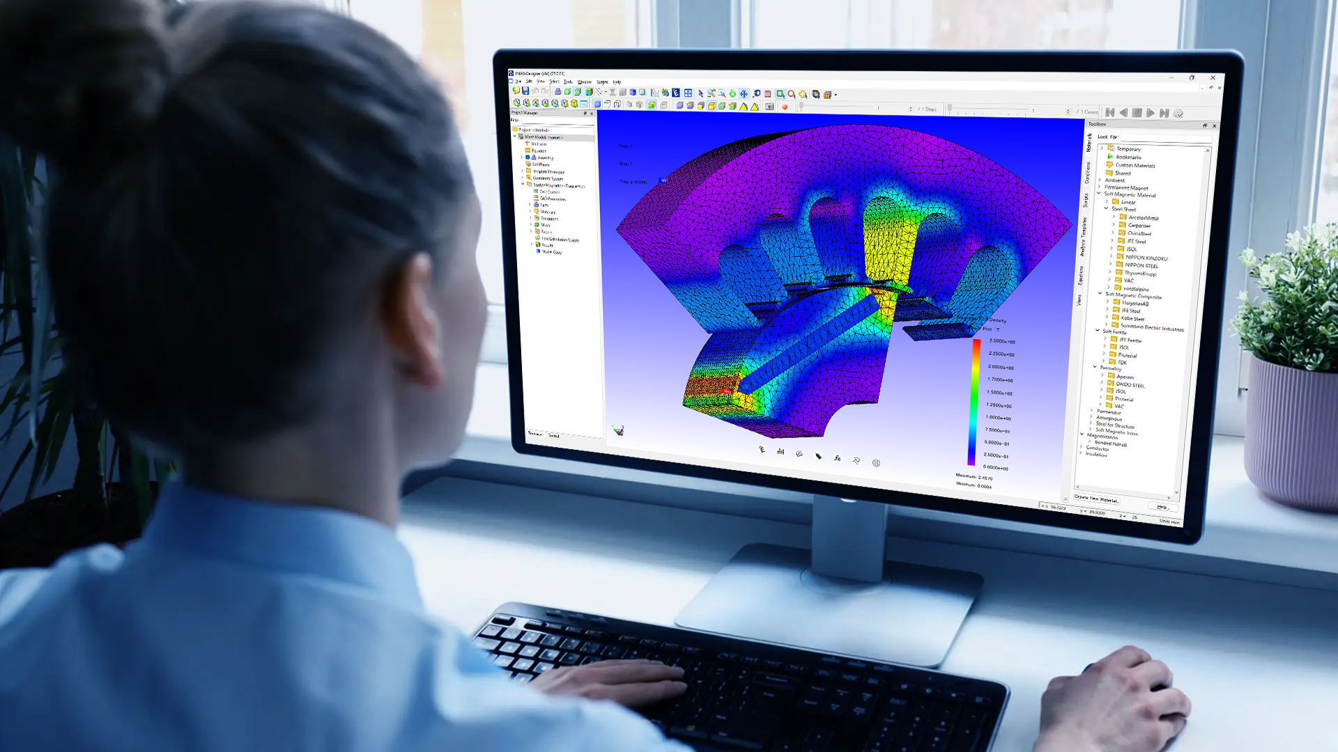
We support sweep-related workflows through our geometric modeling kernels. 3D ACIS Modeler handles geometry creation, surface and solid modeling, modification, and query. Our JMAG case study lists sweep operations — including extrusion and rotation — among the ACIS-based capabilities used in a CAE application.
For developers building CAD, CAM, or CAE applications, sweep support matters because the result has to be more than a visible shape. The generated body must stay topologically valid for whatever comes next — Boolean modeling, filleting, meshing, simulation prep, and export. Our modeling kernels and interoperability tools are built to keep that geometry sound across those workflows.
Want to try it on your own models? Request an evaluation or talk to our team.

-1.webp)


.png?width=450&name=AdobeStock_188705270%20(2).png)


